

Applies low-pass and high-pass filtering to the input signal. Drag the nodes in the filter graph, or adjust the dials below the graph, to adjust the cutoff frequency and resonance of each band.
TIDES VISUALISATION
Access your downloads, purchases and more

Pulse is a revolutionary new downloader offering blazing fast speeds and powerful control over your libraries. Loot Audio uses Pulse to power some of our downloads and to make managing your libraries more efficient for you.
After your purchase we will send you a unique code (you will also find the code in your account). Use the code with Pulse to power your download and installation. More information about Pulse can be found here.
What are Credits?
You earn Credits every time you purchase a product from Loot Audio. 3% of your order is added to your account in the form of Credits.
Use Credits for money off future orders or convert them to Sample Credits to download samples from the Sounds section of the site.
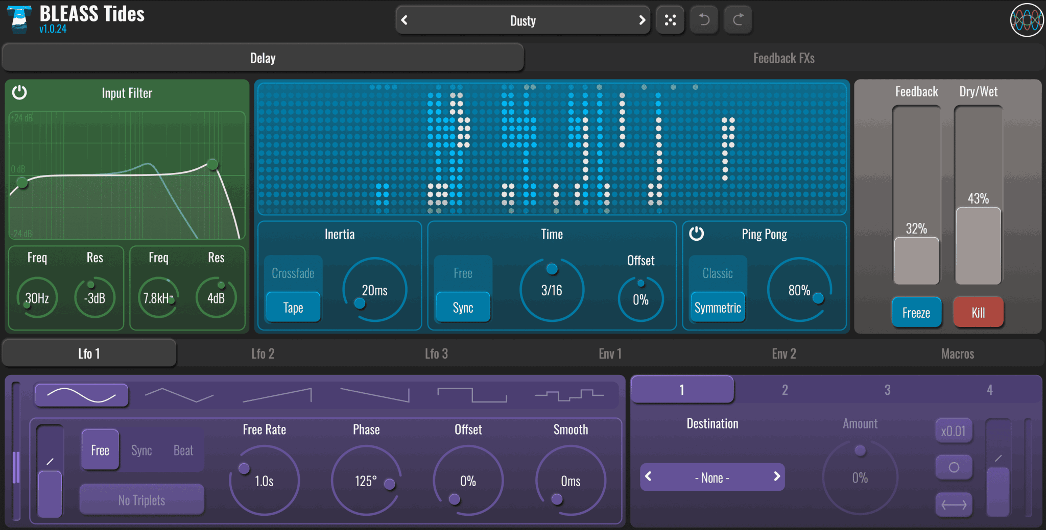
Ride the Waves of Delay
$39.00
Earn 105







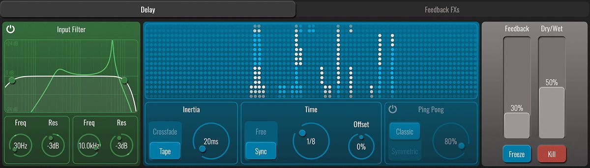
Applies low-pass and high-pass filtering to the input signal. Drag the nodes in the filter graph, or adjust the dials below the graph, to adjust the cutoff frequency and resonance of each band.
TIDES VISUALISATION
This panel provides a lightweight spectral readout of the sounds entering and being produced by BLEASS Tides. The incoming signal’s spectrum is represented by white dots, and repeats are represented by light blue dots.
Touching or clicking on the visualisation activates a frequency shifter within the feedback path (note that this is independent of the optional Frequency Shifter insert processor).
INERTIA
Inertia governs the time it takes for any change in delay time to be applied, as well as the way in which the change will be applied.
TIME
Use the main Time dial to set the desired delay time.
The Offset dial modifies the selected delay time. This is particularly useful when you want repeats to be synchronised to the beat in a natural, non-robotic way.
PING PONG
When Ping Pong is enabled, successive repeats alternate between two channels, with the stereo spread of those channels controlled by the Ping Pong dial.
FEEDBACK
Determines how much signal is fed back to the beginning of the delay processor. Higher values result in more repeats being produced. A setting of 100% will repeat indefinitely.
FREEZE
When this momentary button is pressed, the current delay signal is held and repeated, and the incoming signal does not create any new echoes.
KILL
Press this momentary button to instantly mute the delayed signal and reset the delay processor. Once released, delay processing will resume in the normal way.

Visualises the Envelope Follower’s output.
CURVE FADER
Warps the shape of the Envelope Follower’s attack and release stages.
GAIN
Controls the sensitivity of the Envelope Follower’s transient detection.
ATTACK
Sets the rate of the envelope’s attack stage.
RELEASE
Sets the rate of the envelope’s release stage.
Click on a slot to open a list of processors, and click the processor name to assign it to the slot. Enable or disable a loaded processor using its power button, and reposition it by simply dragging it to a new slot. Note that only one of each processor can be inserted.
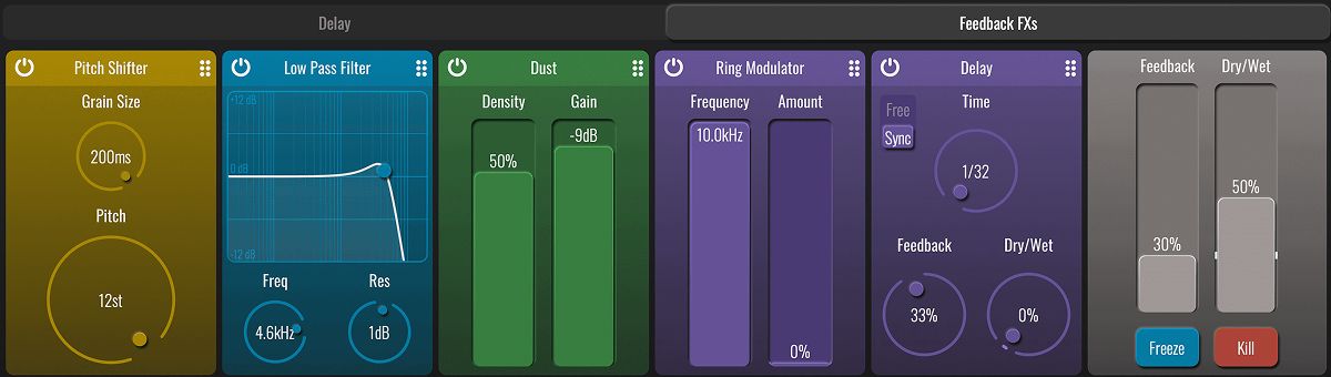
The available processors are:
DISTORTION
Applies any one of three distortion models. Use the selector at the top of the panel to choose the type of distortion, turning the dial to adjust its strength.
Be aware that, by boosting the feedback signal’s strength, this processor can cause a runaway feedback loop. The plugin includes a 0dB limiter on the wet signal that will protect your speakers and equipment, but to stop such a loop simply hit the Kill button.
DUST
Adds random digital noise to the feedback signal for a grittier and dirtier sound. Use the Density fader to control the frequency of the noise, and the Gain fader to control its prominence.
BITCRUSH
Simulates the effects of applying sample rate and/or bit-depth reduction. Use the Downsample dial to reduce the sample rate, and the Bit Depth dial to reduce the sample resolution.
FREQUENCY SHIFTER
Applies a frequency-based pitch shift of up-to ±1kHz to the feedback signal.
PITCH SHIFTER
Applies a granular semitone-based pitch adjustment of up-to ±1 octave to the feedback signal. Lower Grain Size settings work best for short and percussive sounds but produce a more processed/less natural sound than longer settings. Use the Pitch dial to set the amount of shift in semitones.
RING MODULATOR
Applies a ring modulation effect to the feedback path. Use the Frequency fader to set the pitch of the carrier (that is, the sound that will be modulated by the feedback signal). The Amount fader controls the overall strength of the effect.
DELAY
Adds a simple secondary delay line within the feedback path. In Sync mode, delay time is set in terms of note length; in Free mode, delay time is set in milliseconds and seconds.
Be aware that this processor can cause a runaway feedback loop that can get louder and louder. If this happens, hit the Kill button to stop the loop.
HIGH PASS FILTER, LOW PASS FILTER, BAND PASS FILTER
Adds filtering to the feedback path. Drag the filter graph’s node, or use the dials, to adjust the filter’s cutoff frequency and resonance.
PEAK FILTER
Adds a peak filter to the feedback path. Drag the filter graph’s node, or use the dials, to adjust cutoff frequency and gain. The Resonance dial controls the bandwidth of the peak curve.

Specifies the waveform that the LFO will use.
MODULATION METER
Visualises the LFO’s output.
CURVE FADER
Warps the shape of the LFO’s waveform.
SYNC MODE
NO TRIPLETS
When enabled, any triplet value selected for the LFO Rate (1/3, 1/6 etc.) will be ignored. Not available in Free sync mode.
SYNC RATE
Sets the time taken for the LFO to complete one cycle of its waveform. The Rate is expressed as milliseconds and seconds when in FREE sync mode, otherwise it is expressed in terms of note length.
PHASE
Creates a phase offset between the left and right channels of the LFO.
OFFSET
Creates a global phase offset for the LFO.
SMOOTH
Smooths the rate at which the LFO’s output value changes. This is most useful when used with square, sawtooth and sample-and-hold LFO waveforms.

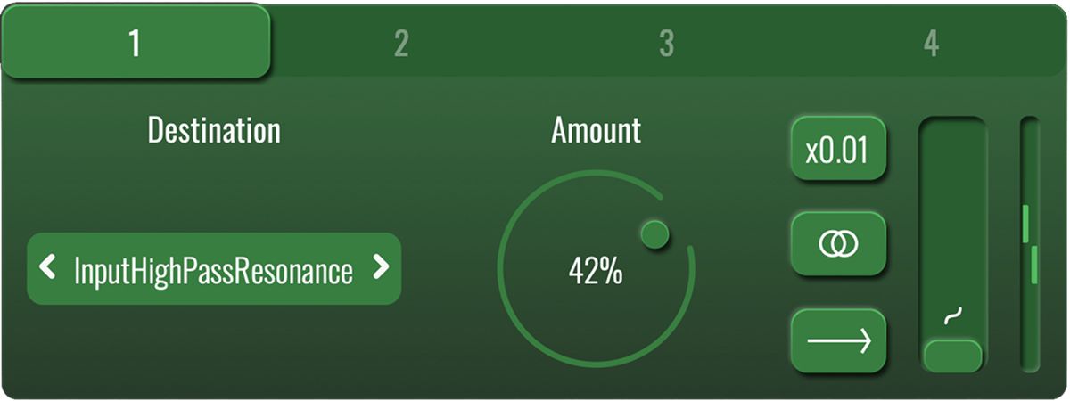
Selects each of the four possible routings for the modulator.
DESTINATION
Specifies the parameter that will be modulated via the routing.
AMOUNT
Determines how strongly the modulator will impact on the destination parameter.
X0.01 BUTTON
Reduces the strength of modulation being sent to the destination by a factor of 100. This makes it easy to create very small fluctuations in the destination parameter’s value.
MONO/STEREO BUTTON
POLARITY BUTTON
MODULATION METER
The meter shown on a Routing Panel visualises the actual strength of modulation being sent to the destination parameter, taking into account all of the routing’s settings.
MAC
WINDOWS